Diesel heaters: fitting, everyday use, fault-finding and repair
A practical owner's and workshop guide to air-type diesel parking heaters: 2, 5 and 8 kW budget units and the Eberspächer and Webasto designs they follow. It covers safety, how they work, fitting in vans, cabs, boats and outbuildings, tuning the hidden settings menu, maintenance, fault codes and electrical tests, a full tear-down and de-coke, alternative fuels and their tax rules in the UK, US and Australia, and water (coolant) heaters.
By Michael Johnson · Updated 16 November 2026 · How we check our guides
Covers: safe use and warnings · fitting · operation · vans, boats and outbuildings · tuning · maintenance · fault-finding · tear-down and repair · alternative fuels · water heaters
This guide is written for a competent DIY fitter or mechanic. It describes the common pattern of air heater: details such as fault-code numbers, connector layouts and torque figures vary between makes and even between batches of the same budget heater. Where a figure is given as 'typical', check it against the data plate and manual for your unit. Follow the heater maker's instructions where they differ from this guide.
1. Safety first: warnings that matter
A diesel heater is a small oil-fired furnace bolted into a vehicle. Fitted and used properly it is one of the safest ways to heat a van, cab, boat or workshop, because the flame and its exhaust are sealed away from the air you breathe. Almost every serious accident comes from one of the five hazards below.
1.1 Carbon monoxide and exhaust gas
- Fit a CO alarm made for vehicles and boats (look for EN 50291-2) in the sleeping area, and test it. A household-only alarm is not built for vibration and damp.
- Never run the heater in a closed garage, workshop or awning unless the exhaust is piped fully outside.
- The silencers supplied with budget kits are folded and spot-welded, not gas-tight. They belong outside the vehicle, never in a locker or under a bed.
- Keep the exhaust outlet away from doors, opening windows, roof vents and the heater's own combustion-air intake.
- Parked against a wall, hedge or snowdrift? Check the exhaust and intake are not blocked before you start it.
- A cracked heat exchanger or a failed burner gasket can let exhaust into the warm air. Any exhaust smell from the hot air vents means: switch off, ventilate, and strip the heater before using it again.
1.2 Fire and heat
- The exhaust pipe runs at several hundred degrees Celsius. Keep it clear of cables, fuel pipe, brake lines, plastic trim, underseal and timber, and use heat wrap or a shield where it passes close to anything.
- Mount the heater on the steel plate supplied, never straight onto plywood or carpet.
- The warm-air outlet is hot enough to scorch. Keep bedding, clothes and aerosols clear, and keep the return-air inlet unobstructed. A starved inlet is the usual cause of overheat shut-downs.
- Do not dry clothes on the heater or over the outlet.
- Carry a fire extinguisher (dry powder or foam, rated for class B liquid fires) within reach of the bed and the door.
1.3 Fuel
- Switch the heater off, and let it finish its cool-down, before refuelling the vehicle or the heater tank and before driving onto a filling-station forecourt.
- Fix the fuel tank where a leak cannot reach the exhaust and where it cannot be crushed in a crash. A tank inside the living space should be sealed and vented outside.
- Use proper small-bore fuel line and clips. Check every joint for weeping after the first few hours of use, and again each season.
1.4 Electrical
- Fit the fuse as close to the battery as possible. A shorted, unfused heater feed will set a loom alight.
- Never cut the power while the heater is running or cooling down. The fan must keep running for several minutes after shut-down to carry heat away. Pulling the fuse or opening a battery isolator leaves the heat exchanger to cook the control board, the fan motor and the plastic case.
- Disconnect the heater's supply before electric welding on the vehicle and before using a boost-starter.
- If the leisure battery has a low-voltage cut-off, set it so the heater's own shut-down happens first.
1.5 Legal, insurance and common sense (UK)
- A heater fitted to a road vehicle should carry a genuine type-approval mark (UNECE Regulation 122 covers heating systems). Marks on budget heaters are not always genuine. Tell your insurer about the installation: it is a modification.
- Vehicles carrying dangerous goods (ADR) and buses have their own stricter rules; a DIY installation is not appropriate there.
- Do not leave a heater running unattended around children or pets who could cover the vents.
- If you are not confident in making gas-tight exhaust joints, fused wiring and leak-free fuel joints, pay a specialist to fit or inspect it.
2. How the heater works
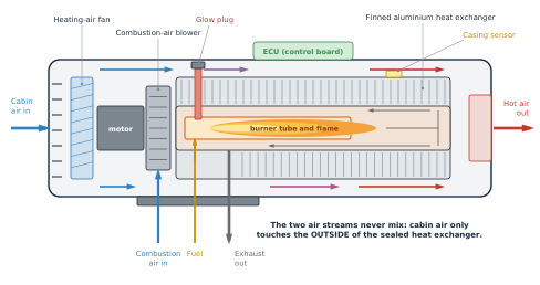
All air-type diesel heaters, from a premium Eberspächer Airtronic or Webasto Air Top to a budget unit, use the same layout. One electric motor drives two fans on a common shaft. A small blower feeds outside air to a burner, where a metered trickle of diesel is vaporised and burned inside a sealed aluminium heat exchanger. A larger fan blows cabin air over the outside of that heat exchanger and into the vehicle.
2.1 The main parts
| Part | What it does |
|---|---|
| Dosing pump | A solenoid piston pump, mounted outside the heater. Each electrical pulse (a 'tick') delivers a fixed tiny shot of fuel. The control board sets heat output by changing the tick rate, roughly 1 to 6 ticks a second. |
| Glow plug | A ceramic or sheathed-metal heating pin. It glows only during start-up to vaporise and light the fuel, and briefly at shut-down to burn the gauze clean. Once the flame is established it switches off. |
| Gauze / atomiser screen | A fine stainless mesh sleeve around the glow plug. Fuel soaks into it and evaporates from its large surface area. |
| Burner (combustion tube) | A perforated stainless tube where fuel vapour mixes with air and burns. Its small air holes are what carbon up when the heater runs cool and rich. |
| Heat exchanger | A finned aluminium casting. Flame and exhaust stay on the inside; cabin air passes over the outside. |
| Motor and fans | One brushed or brushless DC motor: combustion-air blower on one end, heating-air fan on the other. A magnet and Hall sensor report fan speed to the control board. |
| Casing temperature sensor | Clipped to the heat exchanger. The board uses it to confirm the flame has lit (temperature rising), to detect flame-out (temperature falling) and to stop the heater on overheat. |
| Control board (ECU) | Sits under the top cover. Sequences start and stop, modulates pump and fan, and stores fault codes. |
2.2 Start, run and stop sequence
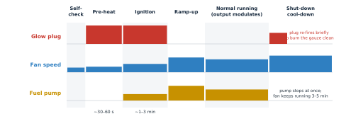
Understanding this sequence makes fault-finding much easier. During pre-heat the plug draws the heaviest current of the whole cycle, so weak wiring shows up here. During ignition the pump starts ticking slowly; you should see a little white vapour at the exhaust that clears within a minute or so as the flame takes hold. If the casing temperature has not risen after the allowed time, most heaters try once more and then lock out with an ignition-failure code. At shut-down the pump stops immediately and the fan runs on until the casing is cool.
2.3 Typical figures
| 2 kW class | 5 kW class | '8 kW' budget class | |
|---|---|---|---|
| Fuel use, low to high | about 0.10–0.25 L/h | about 0.15–0.55 L/h | similar to 5 kW in practice |
| Warm-air duct | 60 mm | 75 mm | 75–90 mm |
| Exhaust / combustion-air pipe | about 24 mm / 25 mm | about 24 mm / 25 mm | about 24 mm / 25 mm |
| Current at start (12 V) | about 8–12 A for a minute or two | about 8–12 A | about 8–12 A |
| Current when running (12 V) | about 0.7–2 A | about 1–3.5 A | about 1–4 A |
| Suits | car, small van, cab | medium or large van, small boat | see note below |
NOTE A litre of diesel holds roughly 10 kWh of heat, so a true 8 kW heater would burn about 0.9 L/h flat out. Many budget heaters sold as 8 kW share the 5 kW casting, pump and burner, and deliver about the same heat. Buy on physical size and fuel consumption, not on the number in the listing. An oversized heater is a nuisance: it spends its life on its lowest setting, which is exactly what soots it up.
2.4 How heat output is controlled: the fuel and air map
The control board does not measure the flame directly. It simply pulses the pump at a chosen rate and spins the fan at the speed its stored settings say belongs with that rate. On budget heaters those settings are just two points, a minimum and a maximum, and the board draws a straight line between them. Every power level you select is a point somewhere on that line.
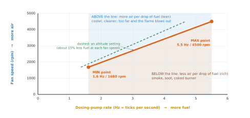
This is why the same heater can burn cleanly or filthily depending on its settings, the fuel and the air density. If the fuel delivered per tick changes (a different pump, a thinner fuel) or the air gets thinner (altitude), the real mixture moves off the line even though the display shows the same numbers. Section 6 explains how to correct it.
2.5 Working out fuel use and heat from the pump rate
Each tick delivers a fixed volume, marked on the pump body: commonly 22 mL per 1,000 strokes on 5 kW budget heaters (smaller-output pumps exist for 2 kW units). So:
Fuel per hour (mL) = pump rate (Hz) × mL per stroke × 3,600
Diesel holds close to 10 kWh per litre. Not all of that reaches the cabin, because some leaves with the exhaust: a reasonable working figure is that about four-fifths becomes useful heat. One independent bench test of a 5 kW budget heater estimated about 3.6 kW delivered from 0.44 L/h at its maximum setting, and about 1.1 kW from 0.13 L/h at minimum.
| Pump rate | Fuel per hour | Fuel in an 8-hour night | Heat in the fuel | Approx. useful heat (80%) |
|---|---|---|---|---|
| 1.2 Hz | 0.10 L | 0.8 L | 1.0 kW | 0.8 kW |
| 1.6 Hz | 0.13 L | 1.0 L | 1.3 kW | 1.0 kW |
| 2.0 Hz | 0.16 L | 1.3 L | 1.6 kW | 1.3 kW |
| 2.5 Hz | 0.20 L | 1.6 L | 2.0 kW | 1.6 kW |
| 3.0 Hz | 0.24 L | 1.9 L | 2.4 kW | 1.9 kW |
| 4.0 Hz | 0.32 L | 2.5 L | 3.2 kW | 2.5 kW |
| 5.0 Hz | 0.40 L | 3.2 L | 4.0 kW | 3.2 kW |
| 5.5 Hz | 0.44 L | 3.5 L | 4.4 kW | 3.5 kW |
NOTE The table assumes a 22 mL per 1,000 stroke pump that really delivers 22 mL. They do not all do so: the bench test mentioned above measured 26 mL per 1,000 strokes from a pump marked 22, which is 18% more fuel than the board believes it is supplying. Section 8.6 shows how to measure yours.
To work out running costs for your own heater, use the diesel heater fuel consumption calculator.
2.6 How the board knows there is a flame
- Budget heaters use a single thermistor clipped to the heat exchanger. A steadily rising reading after the pump starts means 'lit'; a falling reading while fuel is being supplied means 'flame-out'; a reading above the limit means 'overheat'. On one tested unit this sensor was a 50 kΩ NTC type reading about 45 kΩ at 20 °C; other boards use different sensor types, so compare with a known-good part rather than trusting one number.
- Eberspächer Airtronic heaters carry two sensors, a flame sensor and a separate overheat sensor, and compare them: an over-large difference between the two is a fault in its own right.
- Some Webasto units use the glow plug itself as the flame monitor once it has finished heating.
- Practical consequences: a sensor that has come unclipped, or a heater body sitting in an icy draught, can make a perfectly good flame look like a failed start or a flame-out. Always check the sensor is seated before condemning anything else.
3. Fitting the heater
3.1 Planning the position
- Inside the vehicle is the usual and best place for the heater body: it stays dry, and it can recirculate already-warm cabin air. Under a seat, in a bed box or in the base of a cupboard are common spots.
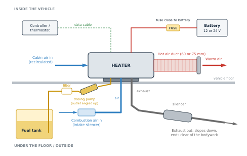
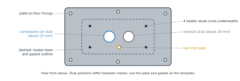
- The three stubs on the base (fuel, combustion air, exhaust) must pass through the floor to the outside. Before drilling, check underneath for chassis rails, fuel tank, brake pipes, wiring and the spare wheel.
- Leave room to lift the top cover and withdraw the glow plug with the heater in place, or accept that servicing means unbolting it.
- Mount it level, base down, glow plug uppermost, unless the maker's manual shows other permitted positions. The burner relies on gravity to keep liquid fuel in the right place.
- Mounting the heater outside (under the floor or in an external box) is done, but it needs weather protection, a ducted return-air feed from the cabin if you want efficiency, and it shortens the life of budget units.
3.2 Mounting plate and floor
- Mark out using the plate or the paper template: one opening (or three holes) for the stubs and four fixing holes.
- Cut the floor opening generously in any timber floor so that no wood sits near the exhaust stub. The steel plate bridges the opening.
- Treat cut metal edges with primer. Seal the plate to the floor with high-temperature sealant so that water, road spray and exhaust cannot enter.
- Fit the rubber base gasket between heater and plate, then tighten the four nuts evenly. This gasket is the seal between 'inside' and 'outside'.
3.3 Exhaust and combustion air
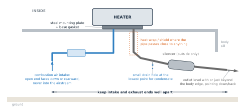
- Keep the exhaust short and with gentle bends. Premium makers typically limit it to about 2 m; a long or tightly bent pipe causes back-pressure, sooting and flame-outs.
- Run it downhill from the heater so condensation drains out. If it must dip, drill a 2–3 mm drain hole at the lowest point.
- End it at or just beyond the edge of the body, pointing down or rearward, not underneath the middle of the vehicle where fumes collect, and not facing forward into the airflow.
- Clamp it to the stub with the proper exhaust clamp and support the pipe every 30–50 cm with P-clips on metal brackets.
- The combustion-air pipe takes clean outside air through the small intake silencer. Keep its open end away from the exhaust outlet, wheel spray and mud, and pointing down or rearward.
- Do not shorten the intake to nothing: the pipe and silencer quieten the roar and stop the blower ingesting spray.
3.4 Fuel system
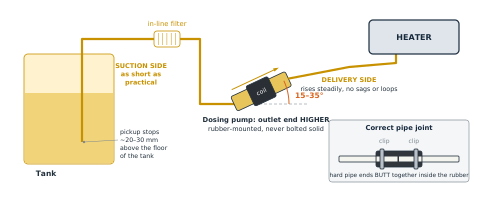
- Supply. Either the separate tank from the kit, or a dedicated standpipe pickup fitted into the vehicle tank. Do not tee into the engine's supply or return line: modern diesel systems are pressurised or under suction, and the heater pump will be starved or flooded. Cut the standpipe so it stops a little above the tank floor, which leaves a reserve so the heater cannot run the vehicle dry.
- Pipe. Use hard, small-bore nylon fuel line (about 2 mm bore) on the delivery side. The narrow bore pushes air bubbles along instead of letting them gather. The soft green pipe in many budget kits is too wide and too flexible; replacing it is the single best upgrade.
- Joints. Cut pipe square with a sharp blade (not side-cutters, which crush it). In each short rubber connector the two pipe ends must butt together, so no pocket is left for a bubble to sit in.
- Filter. Between tank and pump, mounted so it fills fully (outlet uppermost).
- Pump. On the suction side keep the run short and low; on the delivery side let the pipe rise steadily to the heater. Mount the pump in its rubber cradle with the outlet end raised 15–35° so bubbles pass through. Bolting it rigidly to a panel turns the whole body into a sounding board for the tick.
- Routing. Keep fuel pipe away from the exhaust, clip it every 30 cm, and protect it with sleeve where it passes through metal.
3.5 Warm-air ducting
- Shortest and straightest is best. Every bend and every metre of duct costs airflow and raises the heater's internal temperature.
- At least one outlet must be of a type that cannot be closed, so the heater can never be blanked off.
- Give the return-air inlet a clear path to cabin air. If the heater sits in a closed bed box, cut a grille at least the area of the duct. Do not let it suck on bedding or a bag.
- Outlet ducts get hot enough to soften foam and some plastics. Use the proper aluminium/paper or APK ducting and keep it clear of wiring.
- Recirculating cabin air is most efficient. Drawing fresh outside air reduces condensation but uses noticeably more fuel.
3.6 Electrical connection
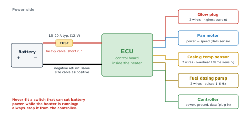
- Connect directly to the battery (leisure battery in a camper) through the fuse, not to a lighting circuit or a cigarette-lighter socket.
- Cable size is where most 'faulty heater' complaints begin. The supplied loom is often thin. As a working guide for 12 V: 2.5 mm² for a run of a couple of metres, 4–6 mm² for longer runs. The aim is to lose well under half a volt during glow-plug pre-heat.
- Crimp and heat-shrink every joint. Twisted-and-taped joints and scotch-lock connectors give trouble within a season.
- Mount the controller at head height away from the hot-air stream and away from draughts if it contains the room-temperature sensor.
- 24 V and 12 V heaters are not interchangeable: glow plug, motor, pump and board are all voltage-specific.
3.7 Choosing the supply cable
Voltage lost in the cable is current × resistance, and the current has to travel out along the positive and back along the negative, so the length that matters is twice the run. For copper: volts lost ≈ 2 × run length (m) × amps × 0.0175 ÷ cable area (mm²). The table works this out for the 10 A or so a 12 V heater draws while the glow plug is on.
| One-way run | 1.5 mm² | 2.5 mm² | 4 mm² | 6 mm² | 10 mm² |
|---|---|---|---|---|---|
| 1 m | 0.23 V | 0.14 V | 0.09 V | 0.06 V | 0.04 V |
| 2 m | 0.47 V | 0.28 V | 0.18 V | 0.12 V | 0.07 V |
| 3 m | 0.70 V | 0.42 V | 0.26 V | 0.18 V | 0.11 V |
| 4 m | 0.93 V | 0.56 V | 0.35 V | 0.23 V | 0.14 V |
| 5 m | 1.17 V | 0.70 V | 0.44 V | 0.29 V | 0.18 V |
| 7 m | 1.63 V | 0.98 V | 0.61 V | 0.41 V | 0.25 V |
Volts lost at 10 A. Green: good. Amber: acceptable with a healthy battery. Red: expect low-voltage faults in cold weather. Fuse holders, crimp joints and connectors each add a little more, so aim for green.
- A 24 V heater draws roughly half the current for the same power, so the same cable loses about a quarter as large a share of the supply.
- Size the fuse to protect the cable, and never raise the fuse rating to cure nuisance blowing.
- If you extend the supplied loom, extend it in the heavier size and keep the original thin section as short as possible.
For other currents and lengths, use the DC voltage drop calculator or the DC cable size calculator.
3.8 Designing the warm-air ducting
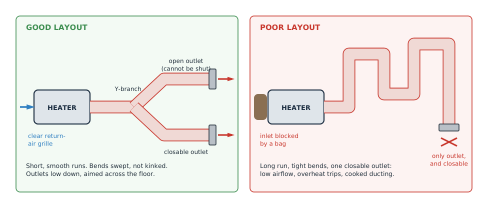
- Think of the heater as a fan with a furnace attached: anything that reduces airflow raises the temperature inside it. Each tight bend costs about as much airflow as a metre or more of straight duct.
- Makers publish a maximum duct length or a 'points' rating for each fitting. With a budget heater that has no such data, keep the total run to a few metres and add a second outlet rather than lengthening a single one.
- A Y-branch splits flow roughly equally; a T-piece favours the straight-through leg. Put the closable outlet on the branch and keep the open one on the main run.
- Insulate ducts that pass through cold lockers, both to keep the heat and to protect whatever is stored beside them.
- Place outlets low, blowing across the floor and away from the return-air inlet. If warm air short-circuits straight back to the inlet, the heater overheats and the cabin stays cold.
- Do not place the controller or its temperature sensor in the outlet air stream, behind a curtain, or near a door.
3.9 Fitting a standpipe to the vehicle tank
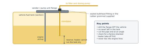
- Check first whether the sender unit already has a blanked auxiliary-heater take-off. Many vans do, and using it avoids drilling.
- Otherwise, run the tank low, disconnect the vehicle battery, clean the top of the tank thoroughly and remove the sender unit. Cover the tank opening while you work.
- On the bench, choose a flat area of the flange clear of the float arm and internal pipes. Drill to suit the standpipe's bulkhead fitting or grommet and deburr; wash away all swarf.
- Cut the standpipe so its end will sit above the engine's own pickup, leaving a reserve, and cut the tip at an angle so it cannot seal against the tank floor.
- Fit and seal the standpipe as its instructions describe, refit the sender with a new sealing ring if one is specified, and check for leaks with a full tank before refitting any trim.
4. Installation variants
Section 3 describes the classic under-seat fit in a van. The same heater ends up in boats, sheds, cabs and portable boxes, and each has its own traps.
4.1 Campervans and panel vans
- Favourite positions: under the passenger seat base (short fuel, exhaust and duct runs), or in the base of a bed box near the sliding door.
- Check the seat base is not already occupied by the battery, a jack or wiring looms, and look underneath for the fuel tank before choosing.
- Feed the heater from the leisure battery so a night's heating cannot flatten the starter battery.
- Route the exhaust to the side away from the sliding door and awning.
4.2 Truck cabs and cars
- Space is tight and the heater is often fitted behind or under the bunk, or under the cab floor in a sealed housing.
- On vehicles carrying dangerous goods, heater installation and operation are regulated; leave these to an approved fitter.
- 24 V vehicles need a 24 V heater. Do not run a 12 V heater from one battery of a 24 V pair: it unbalances the batteries.
4.3 Boats
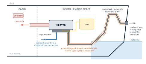
A boat breaks the vehicle rule that the exhaust never runs inside: here it must cross a locker to reach the hull side. That makes the quality of the exhaust the most important part of the job.
- Use a marine installation kit: double-skinned stainless skin fitting, gas-tight marine silencer, and lagging over the entire exhaust run. The folded silencer from a vehicle kit must not be used inside a hull.
- Form a swan-neck so the pipe rises above the outlet before dropping to it, and place the outlet as high above the waterline as possible. A following sea or a heeled hull must not be able to push water back to the heater.
- Mount the heater on a rigid bracket, clear of bilge water, with the stubs down.
- Draw combustion air from a well-ventilated space or from outside, never from a sealed cabin.
- Take fuel from its own tank pickup. A heater must not share a feed with the engine.
- Salt air is hard on budget electronics and connectors: coat plugs with dielectric grease and expect a shorter life.
- On UK inland waterways the installation has to satisfy the Boat Safety Scheme examination. Read the scheme's guidance on fuel, exhaust and ventilation before you start, and tell your insurer.
4.4 Sheds, workshops and garages
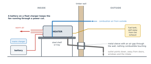
- These heaters are designed and approved for vehicles, not buildings. Fitting one to a building is your own engineering decision; check your buildings insurance.
- Take the exhaust through the wall in a metal sleeve with an air gap, sealed with fire-rated material, so that no timber or insulation touches the hot pipe.
- Use a CO alarm to EN 50291-1 (the household standard) inside the building.
- Power supply: a mains 12 V power supply on its own is a poor choice. It must supply the start surge without sagging, and in a power cut the fan stops dead with the heater at full temperature. A leisure battery kept charged by a mains charger solves both problems.
- Many people instead mount the whole heater outside in a weatherproof box and duct only warm air through the wall. This keeps flame, fuel and exhaust out of the building, at the cost of some efficiency unless a return duct is also fitted.
4.5 Portable all-in-one units
- These have heater, tank and controller in one case, for tents, awnings and occasional use.
- The unit stays outside; only the warm-air duct goes in. Never run one inside a tent or awning, whatever the listing shows.
- Stand it level on firm, non-flammable ground, with the exhaust pointing downwind and away from the tent wall and guy lines.
- The fuel tank sits close to the exhaust in these cases: check for weeps before every trip, and do not refill while it is running.
- Powering one from a small power station works only if the output can supply about 10 A at 12 V for the start without cutting out.
4.6 Heater mounted under the floor or outside
- Use a heater or housing designed for it. A standard unit hung under a floor ingests road spray and salt.
- Without a return duct from the cabin it heats freezing outside air from scratch, which can halve the useful output.
- Protect the loom plugs and the control board from water, and fit drip loops in every cable.
5. Commissioning and everyday use
5.1 First start
- Check: exhaust clamp tight, intake and exhaust ends clear, fuel in the tank, all fuel joints butted and clipped, fuse fitted, CO alarm working.
- Prime the fuel line. Most controllers have a priming mode that runs the pump alone (the key combination differs by controller, so see its leaflet). Run it until fuel, with only the odd small bubble, reaches the heater inlet, then stop. Do not over-prime: fuel pumped into a cold burner makes clouds of white smoke at start-up.
- Start the heater. Expect fan noise, then ticking from the pump, then a low roar. A puff of white smoke and a paint-curing smell on first use are normal.
- If it fails to light, let it finish its purge and try once more. After two failures, stop and find the cause (section 8) rather than keep flooding the burner.
- Run it on high for 20–30 minutes, then check every fuel joint for weeps and the exhaust joints for leaks (sooty streaks, or use a CO meter).
5.2 Good habits
- Stop it from the controller and let the fan run down by itself, every time.
- Avoid long periods at the lowest setting. A cool, lazy flame deposits soot. If you mostly need gentle heat, finish each session with 10–20 minutes on maximum to burn the heater clean.
- Prefer a fixed power setting to a tight thermostat if your controller makes the heater stop and restart often: each start is the hardest, sootiest and most battery-hungry part of the cycle.
- Run it for at least 10 minutes once a month through the summer. This keeps fresh fuel in the pump and stops the pump piston and fan bearings sticking.
- Keep the battery healthy. Low voltage during start-up is the commonest cause of failed starts in cold weather.
5.3 Altitude
Thin air means less oxygen for the same fuel, so the mixture goes rich and the heater smokes and soots. As a rule of thumb, above about 1,500 m a standard heater should only be used briefly unless it is adjusted. Premium heaters offer altitude kits or automatic compensation. Many budget controllers have a hidden settings menu where pump rate can be reduced or fan speed increased: section 6 explains how to use it.
5.4 What the exhaust is telling you
| What you see | Likely meaning |
|---|---|
| Nothing visible, faint hot shimmer | Normal clean running. |
| Brief white vapour at start or stop | Normal: unburnt fuel vapour before the flame is established or as it goes out. |
| Persistent white smoke, sharp smell | Fuel arriving but not burning: failed ignition, flooded burner, weak glow plug, blocked gauze, or water in fuel. |
| Grey or black smoke, sooty outlet | Too rich: restricted combustion air or exhaust, carboned burner, altitude, wrong fuel, or pump set too high. |
| Blue smoke | Oil-based fuel or additive being burned (see section 10). |
5.5 Controller modes and why small vans overheat
- Power (manual) mode holds a fixed pump rate. The heater runs steadily, which is kind to the burner and the battery.
- Temperature (thermostat) mode raises and lowers the pump rate to hold a set temperature. On many budget controllers the heater never switches off in this mode: once at its minimum it simply stays there. In a small, well-insulated van the minimum output can be more than the van loses, so the temperature keeps climbing.
- The cures are a smaller heater, a lower minimum setting (section 6), a little ventilation, or an aftermarket controller that offers a true stop-and-restart thermostat. Bear in mind that every restart costs battery and adds soot.
- Timers and remote starts are convenient, but only use them when you are sure the exhaust and intake are clear and the vehicle is not in a garage or on a ferry deck.
5.6 Fuel and battery budgets
Fuel per night follows from the table in section 2.5. As a guide, a 5 kW heater ticking over uses around a litre in eight hours, and about three and a half litres flat out.
| Running state (12 V) | Typical current | Used in 8 hours | Used in 12 hours |
|---|---|---|---|
| Low output | about 1.0 A | 8 Ah | 12 Ah |
| Medium output | about 2.0 A | 16 Ah | 24 Ah |
| High output | about 3.5 A | 28 Ah | 42 Ah |
| Each start (glow plug) | about 10 A for 2–3 minutes | about 0.4–0.5 Ah per start | |
| Each shut-down (fan run-on, plug re-fire) | varies | about 0.2–0.4 Ah per stop |
- Only about half the rated capacity of a lead-acid leisure battery is usable without shortening its life, and less in the cold. A 100 Ah lead-acid battery therefore comfortably covers one cold night on medium, not three.
- Lithium (LiFePO4) batteries give nearly their full capacity and hold voltage well during the start, but most must not be charged below freezing.
- The amp-hours matter less than the voltage at the heater during the start. A large but tired battery still gives low-voltage faults.
To size the battery for your own heating hours, try the battery run time calculator.
5.7 Cold-weather operation
- Fuel waxing is the main enemy. Wax crystals block the filter and the fine-bore pipe long before the fuel looks cloudy in the tank. UK winter-grade diesel is specified to pass a filter down to −15 °C and summer grade only to −5 °C. For colder trips use alpine or arctic diesel bought locally, HVO, or a kerosene blend (section 10).
- Keep as much of the fuel line as possible inside the heated space, and insulate exposed sections.
- Start the heater before the vehicle is deeply cold. A battery at −10 °C delivers noticeably less current, exactly when the glow plug needs most.
- Condensation freezes. Check the exhaust drain hole is not iced up, and that snow has not buried the exhaust or intake.
- Fit the dosing pump where it stays reasonably warm but never where leaking fuel could reach the exhaust.
- Leave a roof vent slightly open. A sealed van fills with moisture from breathing and cooking, and damp air feels colder.
6. Tuning and the hidden settings menu
Most budget controllers contain a password-protected engineering menu that sets the two ends of the fuel and air map described in section 2.4. Used carefully it cures smoke, soot and altitude problems. Used carelessly it overheats the heater or fills the burner with carbon. Premium heaters do not offer this: their maps are fixed and altitude is handled by a sensor or a dealer tool.
6.1 Getting in
On the common blue-LCD controller, the engineering menu is reached from the settings screen by entering the code 1688. Other controllers use different key sequences, and some simple rotary or four-button controllers have no such menu at all. Aftermarket controllers expose the same values more conveniently.
6.2 What the settings mean
| Setting | What it does | Commonly reported values |
|---|---|---|
| Minimum pump rate (Hz) | Fuel delivered at the lowest power level. | About 1.3–1.6 Hz on 5 kW units; around 1.4 Hz on 2 kW units |
| Maximum pump rate (Hz) | Fuel delivered at full power. Sets maximum heat and maximum casing temperature. | About 5.0–5.5 Hz on 5 kW units |
| Minimum fan speed (rpm) | Air supplied with the minimum pump rate. | About 1,450–1,680 rpm |
| Maximum fan speed (rpm) | Air supplied with the maximum pump rate. | About 4,500 rpm |
| System voltage | 12 V or 24 V. Must match the heater hardware. | As per data plate |
| Fan magnet setting (shown as SN-…) | Tells the board how many pulses the fan sensor gives per revolution. | Leave as supplied unless the motor has been changed |
| Glow plug type (shown as PF-…) | Sets how hard the plug is driven. | Leave as supplied unless the plug type has been changed |
6.3 A safe tuning method
- Service the heater first. Tuning cannot fix a blocked gauze, an air leak in the fuel line or a restricted exhaust.
- Measure the pump's real delivery (section 8.6). If it over-delivers, that alone explains a rich burn.
- Run the heater at maximum for 15 minutes outdoors and watch the exhaust. Any visible smoke once fully warm means too rich. Reduce the maximum pump rate by 0.1–0.2 Hz, wait five minutes, and look again. Repeat until the exhaust is clear.
- Switch to minimum and wait ten minutes. If it smokes, smells or the flame hunts, raise the minimum fan speed by 50–100 rpm or reduce the minimum pump rate by 0.1 Hz.
- If the flame goes out at minimum, you have gone too lean or too low: restore the previous value.
- Return to maximum and confirm the heater does not trip on overheat with all ducts connected.
- Record the new values with the date and the fuel in use.
6.4 Altitude and fuel changes
- Air density falls by roughly 10–12% for every 1,000 m climbed. To keep the mixture the same, reduce both pump rates by about the same percentage and leave the fan speeds alone: for example 5.5 Hz becomes about 4.7 Hz at 1,500 m.
- Heat output falls by the same proportion. That is unavoidable: there is less oxygen to burn fuel with.
- Thinner fuels such as kerosene change how much the pump delivers per tick and how readily it vaporises. Re-check the exhaust at both ends of the range after any change of fuel.
- Restore the original values when you return to low altitude or to diesel.
6.5 Lowering the minimum for a small space
Reducing the minimum pump rate, with the minimum fan speed reduced in step, gives a gentler tick-over. There is a floor: below roughly 1.2 Hz most burners no longer stay hot enough to vaporise fuel cleanly, and the result is soot and flame-outs. If you run a lowered minimum, the habit of finishing each session on maximum becomes essential.
6.6 Symptoms of wrong engineering settings
| Symptom | Setting to check |
|---|---|
| Fan fault as soon as the motor starts, after a board or motor swap | Fan magnet setting does not match the motor |
| Voltage faults on a healthy supply | System voltage set wrongly |
| Glow plugs failing every few weeks, or very slow ignition | Glow plug type setting does not match the plug fitted |
| Overheat trips at full power with clear ducts | Maximum pump rate set too high, or pump over-delivering |
| Smoke only at the lowest setting | Minimum fan speed too low for the minimum pump rate |
7. Maintenance
These heaters need little attention if they are run hot and fed clean fuel. Neglected or run cold, they clog with carbon. The schedule below suits regular winter use; halve the intervals for full-time living aboard.
| When | Job |
|---|---|
| Every use | Glance at the exhaust and intake ends. Listen for a steady pump tick and a smooth fan. Stop it from the controller. |
| Monthly, all year | Run for 10+ minutes, with the last few minutes on maximum. Test the CO alarm. |
| Start of each heating season | Check fuel pipe, joints and clips for cracks or weeping. Check exhaust and its clamps for corrosion, splits and soot streaks. Check intake pipe and silencer are clear (insects and mud). Clean battery and fuse connections. Vacuum dust from the return-air inlet and fan. |
| Yearly, or about every 500 running hours | Renew the in-line fuel filter. Drain water and sludge from a separate heater tank. Remove the glow plug, inspect it and clean or renew the gauze (section 9.1). |
| Every 2–3 years, or when starting gets slow or smoky | Full strip and de-coke of burner and heat exchanger with new gaskets (section 9.2). |
| About 10 years (premium heaters) | Makers such as Webasto specify renewing the heat exchanger at around ten years from first use, because of thermal fatigue. |
7.1 Fuel care
- Diesel ages. Fuel left in a small vented tank over summer absorbs moisture and can grow 'diesel bug' sludge that blocks the filter and pump. Start each season with fresh fuel.
- In hard frost, ordinary diesel can wax and block the filter and small-bore pipe. UK forecourt diesel is winter grade from mid-November to mid-March; summer fuel left in a heater tank is not.
- Never let the tank run dry: the pump relies on fuel for lubrication and cooling, and you will have to re-prime.
7.2 Spares worth carrying
- Glow plug of the correct voltage, and its removal tool.
- Two or three gauze screens.
- Gasket set (burner, blower and base gaskets).
- Fuel filter, a length of hard fuel pipe, rubber joiners and clips.
- Spare fuses.
- A dosing pump is cheap and worth having on a long trip.
7.3 Laying up and recommissioning
Before a long lay-up:
- Run the heater on maximum for 20–30 minutes so it is put away clean and dry.
- Either brim a separate heater tank to keep moist air out, or drain it completely. A half-full vented tank is the worst case.
- Cap or cover the exhaust and intake ends loosely to keep insects out, and hang a tag on the controller to remind you.
- Leave the battery charged or on a maintenance charger.
Bringing it back into use:
- Remove the covers. Check both pipes for nests, mud and corrosion.
- Renew the fuel filter and put in fresh fuel. If the old fuel smells sour or looks hazy, drain it.
- Check fuel joints by eye and by touch. Hardened rubber joiners are cheap to replace.
- Prime, start, and run on high outdoors. Expect a little smoke from dust burning off.
8. Fault-finding and electrical tests
8.1 Fault codes: budget heaters
The table shows the numbering used by the common blue-LCD budget controllers. Numbering is not universal: other controllers and the premium makes use different lists, so confirm against the leaflet for your controller.
| Code | Usual meaning | First things to check |
|---|---|---|
| E-01 | Supply voltage too low | Battery charge; voltage at the heater plug during start; cable size; corroded fuse holder and joints. |
| E-02 | Supply voltage too high | Charger or alternator over-voltage; 12 V unit on a 24 V supply. |
| E-03 | Glow plug fault | Plug connector; plug open or short circuit (measure resistance); board driver. |
| E-04 | Fuel pump circuit fault | Pump plug and loom for breaks or shorts; pump coil. |
| E-05 | Overheat | Blocked return-air inlet, crushed or closed ducts, too much duct, dust-choked fan; then the sensor itself. |
| E-06 | Fan motor fault | Fan jammed or rubbing; motor plug; Hall-sensor magnet missing or cracked; worn brushes or bearings. |
| E-07 | Communication fault | Controller cable and plugs; damaged loom; remote-receiver fault. |
| E-08 | Flame-out while running | Air in fuel line, fuel starvation, waxed fuel, blocked filter, carboned burner, blocked exhaust, voltage sag. |
| E-09 | Temperature-sensor fault | Sensor plug loose; sensor open or short circuit. |
| E-10 | Failed to ignite | No fuel (prime it), weak glow plug, blocked gauze, low voltage, blocked exhaust or intake, water in fuel. |
8.2 Step-by-step when it will not run
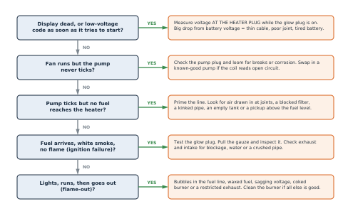
- Display dead, or low-voltage code as soon as it tries to start? Measure voltage at the heater plug while the glow plug is on. A big drop from battery voltage means thin cable, a poor joint or a tired battery.
- Fan runs but the pump never ticks? Check the pump plug and loom for breaks or corrosion. Swap in a known-good pump if the coil reads open circuit.
- Pump ticks but no fuel reaches the heater? Prime the line. Look for air drawn in at joints, a blocked filter, a kinked pipe, an empty tank or a pickup above the fuel level.
- Fuel arrives, white smoke, no flame (ignition failure)? Test the glow plug. Pull the gauze and inspect it. Check exhaust and intake for blockage, water or a crushed pipe.
- Lights, runs, then goes out (flame-out)? Bubbles in the fuel line, waxed fuel, sagging voltage, coked burner or a restricted exhaust. Clean the burner if all else is good.
8.3 Simple bench tests
| Component | Test | Good result (typical) |
|---|---|---|
| Supply | Voltmeter across the heater's main plug while the glow plug is heating. | Within about 0.5 V of battery voltage; comfortably above 12 V on a 12 V system. |
| Glow plug | Unplug it; measure resistance across its two wires, cold. Subtract the meter's own lead resistance. | A low reading, typically from under 1 Ω to a couple of ohms for 12 V plugs and a few ohms for 24 V. Open circuit or dead short = scrap. |
| Dosing pump | Unplug from the loom and briefly pulse with the correct voltage: it should click sharply. Measure coil resistance. | A clean click each pulse and a steady coil reading; open circuit = scrap. Pump output can be checked by collecting fuel over a counted number of ticks and comparing with the figure marked on the pump (commonly 22 mL per 1,000 strokes). |
| Temperature sensor | Measure resistance cold, then warm it in the hand. | A stable reading that changes smoothly as it warms. Open circuit, short or jumpy = renew. |
| Fan motor | Spin by hand with power off; then observe on start. | Free and quiet, no rubbing. Speed should rise smoothly through the start sequence. |
8.4 Eberspächer / Espar Airtronic fault codes
Read out on the EasyStart controller, a diagnostic tool or the dealer software. A selection of the most useful codes for the Airtronic D2 and D4 family:
| Code | Meaning | Notes |
|---|---|---|
| 010 / 011 | Over-voltage / under-voltage cut-off | Must persist for about 20 seconds. Over-voltage is above about 16 V (12 V units) or 32 V (24 V units). |
| 012 / 013 | Overheating at the overheat sensor / at the flame sensor | Check ducting and airflow first. |
| 014 | Flame and overheat sensors disagree by too much | Sensor position or sensor fault. |
| 015 / 017 | Locked out after overheating | Needs the fault memory cleared before it will run. |
| 020 / 021 | Glow plug open circuit / short or overload | Plug should read about 0.6 Ω (12 V) or about 2 Ω (24 V). |
| 031–034 | Blower motor open, shorted, or wrong speed | 033 means stuck, or more than 10% off its target speed for 30 seconds. |
| 047 / 048 | Metering pump short circuit / open circuit | Pump coil should read about 9.5 Ω (12 V) or about 36 Ω (24 V). |
| 050 | Too many failed starts: locked out | Find the cause, then clear the fault memory. |
| 051 | Flame detected at switch-on | Flame sensor fault, or heater still hot. |
| 052 | No flame within the safety time | Fuel supply, glow plug, exhaust and intake. |
| 053–056 | Flame went out at Power / High / Medium / Low stage | Fuel starvation, air in the line, carbon. |
| 060–065 | Room sensor, control unit or flame sensor open or shorted | |
| 071 / 072 | Overheat sensor open / shorted | |
| 090–099 | Control box internal faults | 099 can be caused by supply voltage dipping very low. |
NOTE Unlike budget heaters, an Eberspächer that has failed to start or has overheated several times in a row locks itself out on purpose. Repeatedly switching it on will not clear this: the stored faults have to be deleted with the controller's service function or a diagnostic tool.
8.5 Webasto Air Top 2000 STC fault codes
Shown on the timer display, or flashed on the control dial's lamp as a count of slow flashes after a burst of quick ones.
| Code | Meaning |
|---|---|
| F00 | Control unit defective |
| F01 | No start |
| F02 | Flame failure |
| F03 | Supply voltage out of range |
| F04 | Flame detected before combustion |
| F05 | Flame sensor interrupted |
| F06 | Temperature sensor interrupted |
| F07 | Fuel pump interrupted |
| F08 | Combustion-air fan shorted or blocked |
| F09 | Glow plug circuit interrupted |
| F10 | Heater overheated |
| F11 | Overheat sensor interrupted |
| F12 | Heater locked out |
| F14 | Temperature rise too slow during start |
| F15 | Set-point potentiometer interrupted |
8.6 Measuring what the dosing pump really delivers
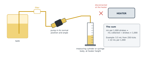
- Switch off and let the heater cool. Put rag under the heater's fuel inlet and pull the fuel pipe off its stub.
- Lead the pipe into a small measuring cylinder, or the barrel of a 10–20 mL syringe, held at about the height of the heater inlet.
- Run the controller's priming mode until fuel flows without bubbles, then empty the cylinder.
- Run priming again and count the ticks: 250 is a convenient number. Stop and read the volume.
- Divide the volume by the number of ticks and multiply by 1,000. Compare with the figure marked on the pump. (Example: 5.5 mL from 250 ticks = 22 mL per 1,000.)
- Refit the pipe, making sure it is pushed fully home, and wipe up.
- Within about 10% of the marked figure is fine. Well over: the heater runs rich and sooty; correct it in the settings (section 6) or change the pump. Well under, or erratic: look for air leaks on the suction side, a blocked filter or a worn pump.
- Premium makers give an exact test in the workshop manual, with a fixed run time and an acceptable volume range for each model.
8.7 Electrical test points
With the top cover off, each component plugs into the board separately, which makes testing straightforward. Connector shapes and wire colours differ between makes, so trace each lead to its component rather than relying on colour. Unplug before measuring resistance.
| Lead | How to recognise it | What to measure | Expect |
|---|---|---|---|
| Main supply | Two heavy wires from the loom | DC volts at the board during pre-heat | Close to battery voltage; see section 3.7 |
| Glow plug | Two fairly heavy wires disappearing under a rubber cap on top of the casting | Resistance, cold | Low: under 1 Ω up to a couple of ohms (12 V). Open circuit = failed |
| Fan motor | Lead entering the blower end of the heater | Resistance across the motor wires; spin test | A low, steady reading on brushed motors; a jumpy reading as you turn it suggests worn brushes |
| Fan speed sensor | Extra thin wires in the motor lead, or a sensor on the board beside the fan | DC volts on the signal wire while turning the fan slowly by hand | Should switch cleanly between high and low as the magnet passes |
| Casing sensor | Two thin wires to a tab clipped to the heat exchanger | Resistance cold, then warmed | A steady value that moves smoothly with temperature (about 45–50 kΩ at 20 °C on the common NTC type) |
| Dosing pump | Two wires leaving in the main loom to the pump | Resistance at the pump plug | A steady coil reading, typically from about ten to a few tens of ohms depending on make and voltage. Open circuit = failed |
| Controller | Three or four thin wires to the display | Supply volts at the controller plug | Supply present; if so and the display is dead, suspect the controller |
8.8 Control board faults
- The commonest board failure is the glow-plug driver. If a known-good plug gets no voltage during pre-heat, the board needs repair or replacement.
- Look for browned or melted connector housings, especially the glow plug and main supply plugs. A poor contact heats up, which makes it worse.
- Green or white corrosion on the pins means water has got in. Clean with contact cleaner and find the route the water took.
- A replacement board must match the heater's voltage, power class, motor type and controller. Budget boards and controllers are sold as matched families and do not all talk to each other.
- After fitting a new board, check the engineering settings (section 6) before the first start.
8.9 Symptom index
| Symptom | Most likely causes, in order |
|---|---|
| Nothing at all, display blank | Fuse; supply plug; controller cable; controller; board |
| Starts its fan, then stops with a voltage fault | Voltage drop in the supply cable; weak battery; corroded fuse holder |
| No ticking from the pump | Pump plug or loom; pump coil; board output |
| Ticks, white smoke, never lights | Glow plug; gauze; over-priming; water in fuel; blocked exhaust |
| Lights then dies after a minute or two | Air in the fuel line; sensor not seated; restricted fuel supply |
| Runs for an hour then flames out | Fuel waxing; tank vent blocked (vacuum in the tank); filter partly blocked; voltage sagging as the battery drains |
| Black smoke and soot | Blocked intake or exhaust; carboned burner; pump over-delivering; altitude |
| Overheat trips | Ducting too long or shut; return air blocked; dust on the fan; maximum pump rate too high |
| Surging or 'hunting' roar | Air bubbles in the fuel; pump mounted flat or outlet-down; loose fuel joint |
| Loud ticking in the cabin | Pump bolted to a panel; soft wide-bore pipe; pipe touching bodywork |
| Whine or rattle from the heater | Fan bearings; impeller rubbing; debris in the fan |
| Fuel smell | Weeping joint; over-priming; fuel dripping from the exhaust after failed starts |
| Exhaust smell in warm air | Stop using it. Failed gasket, cracked heat exchanger, or exhaust drawn into the air inlet |
| Heater will not switch off | Normal for several minutes: it is cooling down. If the fan never stops, suspect the casing sensor |
| Fuel dripping from exhaust | Repeated failed starts have flooded the burner. Let it drain, find the ignition fault, expect heavy smoke on the next start |
9. Tear-down and repair
9.1 Glow plug and gauze service (heater left in place)
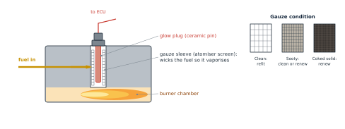
- Switch off at the controller, wait for the cool-down to finish, then pull the fuse.
- Release the top cover (clips or screws) and lift it off. Photograph the board and its plugs before disturbing anything.
- Unplug the glow-plug lead from the board and pull off the rubber cap or grommet over the plug.
- Unscrew the plug with the thin box spanner supplied with the heater. Work gently: ceramic plugs snap if levered sideways.
- Look down the bore with a torch. Hook the gauze out with a bent wire, a small pick or the tool supplied. Note which way up it sat; most have a slot or seam that lines up with the fuel inlet hole.
- Judge it against the gauze-condition drawing above (clean: refit; sooty: clean or renew; coked solid: renew). Light soot can be burned off with a blowlamp until the mesh glows clean, but gauzes are cheap and a new one is the better fix.
- Scrape loose carbon from the bore, and make sure the small fuel inlet hole in the side of the bore is open.
- Fit the gauze fully home, refit the plug finger-tight plus a light nip (it seals on a taper or washer and strips easily), reconnect, refit the cover and test.
9.2 Full tear-down and de-coke
Symptoms that call for a full strip: slow, smoky starts that a new plug and gauze did not cure; repeated flame-outs with good fuel and voltage; black smoke; or soot found in the exhaust stub. Buy a gasket set first. Old gaskets must not be reused, because they are what keeps exhaust gas out of your warm air.
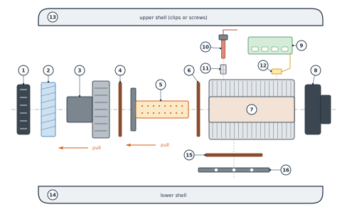
| No. | Part | No. | Part |
|---|---|---|---|
| 1 | Inlet end cap / grille | 9 | Control board (ECU) |
| 2 | Heating-air fan (impeller) | 10 | Glow plug |
| 3 | Motor with combustion-air blower housing | 11 | Gauze / atomiser screen |
| 4 | Blower-to-exchanger gasket | 12 | Casing temperature sensor |
| 5 | Burner (combustion tube) on its flange | 13 | Upper shell |
| 6 | Burner gasket | 14 | Lower shell |
| 7 | Aluminium heat exchanger | 15 | Base gasket |
| 8 | Outlet end cap / duct spigot | 16 | Steel mounting plate |
Removal from the vehicle. Isolate the supply. Clamp or plug the fuel line and release it at the heater stub. Release the exhaust and intake clamps underneath, pull off the ducts, unplug the main loom, undo the four base nuts and lift the heater out. Work on a clean bench.
Strip-down order.
- Shells (13, 14). Unclip or unscrew the top cover and end caps (1, 8), then separate the two shell halves. Plastic clips are brittle when cold, so warm the case indoors first.
- Control board (9). Photograph, then unplug every connector: main loom, fan motor, glow plug, temperature sensor (the pump and controller usually join the main loom). Lift the board out and put it somewhere dry and static-safe.
- Sensor (12). Unclip or unscrew it from the heat exchanger. Note its exact position.
- Glow plug and gauze (10, 11). Remove as in section 9.1.
- Fan and blower assembly (2, 3). Undo the ring of screws (usually four) holding the blower housing to the heat exchanger. Draw the assembly straight off along the centre line and peel off gasket 4. Feed the motor lead and its grommet out carefully.
- Burner (5). Now visible inside the mouth of the exchanger, held by a few screws through its flange. These are often seized by heat: soak with penetrating oil, use a well-fitting bit and steady pressure. Withdraw the burner and peel off gasket 6.
- Heat exchanger (7). Nothing further to remove; it is one casting.
Cleaning.
- Burner: scrape and wire-brush the tube, and clear every air hole with a drill bit turned in the fingers. Hard glazed carbon can be burned off with a blowlamp outdoors. Renew the burner if the tube is cracked, distorted or burned through.
- Heat exchanger: scrape the inside with a long screwdriver or a length of chain shaken around inside it, tip out the debris, and finish with a vacuum cleaner. Make sure the exhaust port and the fuel inlet drilling are clear. Soaking in a strong degreaser or caustic solution works on stainless parts but attacks aluminium, so keep caustic cleaners away from the casting.
- Inspect the casting for cracks, especially around the burner seat and the exhaust port. A cracked heat exchanger is scrap: there is no safe repair.
- Blower: brush dust from both impellers and check they spin freely with no bearing rumble. Check the Hall-sensor magnet is present and secure.
- Mating faces: remove every trace of old gasket with a plastic scraper; do not gouge the aluminium.
Reassembly. Reverse the order with new gaskets 4, 6 and 15, dry, with no sealant on the hot joints. Tighten flange screws evenly and in a cross pattern; they thread into aluminium, so stop at firm. Make sure no wire is trapped between the shells or touching the heat exchanger. Refit to the vehicle, re-prime, and run on high for 20 minutes outdoors with the CO alarm beside the hot-air outlet before trusting it overnight. Expect a little smoke at first as cleaning residues burn away.
9.3 The burner in detail
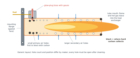
- Fuel arrives at the gauze in the glow-plug boss, evaporates, and is carried into the tube by air entering through the small holes nearest the flange.
- Further along, larger holes add the rest of the air so combustion finishes before the gas leaves the tube mouth.
- Carbon forms first where the metal is coolest and the mixture richest: the gauze, the first ring of small holes and the bore of the glow-plug boss. A burner can look clean at the mouth and be nearly blocked at the flange end.
- After cleaning, hold the tube up to a light and confirm that every hole is open and round.
- Renew the burner if you find cracks between holes, a tube that has gone oval, scaling that flakes away, or a distorted flange that will not sit flat.
9.4 Motor, blower and speed sensor
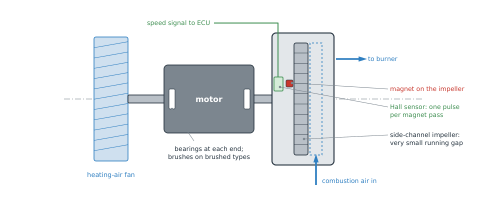
- The combustion blower is a side-channel type: the impeller runs with a very small gap to its housing. Any carbon, corrosion or a bent impeller makes it rub, which is heard as a screech and seen as a fan fault.
- The board counts pulses from a magnet on the impeller. A magnet that has fallen out, been refitted the wrong way round, or cracked gives a fan fault even though the motor spins.
- Brushed motors eventually wear their brushes. Symptoms are a fan that needs a flick to start, or cuts out when hot.
- Do not lubricate sealed bearings with thin oil: it washes the grease out. Noisy bearings mean a new motor or bearing set.
- When refitting, make sure the gasket is not pinched into the air path and the motor lead grommet is seated, or the housing will leak air.
9.5 Differences on 2 kW units
| Item | 2 kW class | 5 kW class |
|---|---|---|
| Body and ducting | Smaller casting, 60 mm duct | Larger casting, 75 mm duct |
| Burner and gaskets | Smaller; not interchangeable | Larger |
| Dosing pump | Often a smaller-delivery pump: check the marking | Commonly 22 mL per 1,000 strokes |
| Glow plug and gauze | Usually the same type as the 5 kW from the same maker | |
| Strip-down | Same order. Fewer flange screws on some; access to the burner screws is tighter | As described in section 9.2 |
| Settings | Lower pump rates throughout | See section 6.2 |
TIP When ordering spares for a budget heater, measure the old part and order by dimensions and photographs. Listings titled 'fits 2 kW / 5 kW / 8 kW' are frequently wrong for at least one of them.
9.6 Other common repairs
| Fault | Repair |
|---|---|
| Noisy or seized fan | Bearings are sometimes replaceable on brushless motors; on budget brushed motors a complete motor/blower assembly is the practical fix. |
| Pump ticks but delivers little | Flush with clean diesel; check the tiny inlet strainer some pumps have; otherwise renew. Do not dismantle the piston. |
| Loud pump tick | Rubber-mount the pump, use hard nylon pipe, and keep the pump off resonant panels. |
| Controller blank | Check fuse, then supply at the board plug, then the controller cable. Boards fail from over-voltage, reverse polarity and from power being cut while hot. |
| Heater overheats on long ducts | Shorten or enlarge the ducting, add a second outlet, clear the return-air path. |
| Diesel smell in the cabin | Weeping fuel joint, or an exhaust leak drawn back in. Find it before using the heater again. |
10. Alternative fuels
The heater is a vaporising burner tuned for road diesel (EN 590). It will burn other light distillates, but each one changes how cleanly it burns, how well the dosing pump is lubricated, and whether the maker (and your insurer) still stands behind it. The premium makers publish approved-fuel lists that differ by model, so check the manual for your exact heater. Budget heaters carry no meaningful approvals for anything but diesel.
| Fuel | Suitability | Notes |
|---|---|---|
| Road diesel (EN 590, up to 7% biodiesel) | Designed for it | Use winter grade in frost. Fresh fuel each season. |
| HVO / GTL paraffinic diesel (EN 15940) | Very good | Burns cleaner with less soot and smell, stores far better than ordinary diesel and resists cold well. Approved by Webasto for its heaters; widely used in budget units without modification. |
| Kerosene / paraffin (28-second heating oil), Jet A-1 | Works; cleaner burn, with cautions | Thinner, vaporises easily, soots much less and handles cold well. It lubricates the pump less than diesel, and it burns slightly differently, so some heaters run a little hotter or need the pump rate trimmed. Some premium models list kerosene as permitted; others do not. A diesel/kerosene blend is a common cold-weather compromise. |
| Red diesel / gas oil (35-second heating oil) | Works; quality varies | Chemically close to road diesel. Off-road and heating grades can have higher sulphur and poorer cold performance, which shortens burner life. |
| Biodiesel blends above B7, B100 (FAME) | Model-dependent; generally avoid in budget heaters | Thickens and gels in cold, absorbs water, ages quickly and can soften some rubber parts. A few premium models are approved for B100; most heaters are approved only for normal pump blends. |
| Vegetable oil, waste cooking oil | Not recommended | Far too viscous for the dosing pump and gauze when cold; polymerises into hard varnish. Even small percentages blended into diesel coke the burner quickly. |
| Waste engine oil, hydraulic oil, ATF | Do not use | Contains metals and additives that do not vaporise. They glaze the gauze and burner, and the exhaust is toxic. Sold-as-'waste oil' heater conversions need frequent strip-downs at best. |
| Petrol, or petrol/diesel mixes | NEVER | Explosion and fire risk in a diesel heater. |
| White spirit, thinners, alcohol, solvents | NEVER | Wrong volatility and no lubrication; dangerous. |
10.1 How the fuels compare
Typical published values. Individual batches vary, and cold-weather figures in particular depend on the season and the supplier.
| Property | Road diesel (EN 590) | HVO (EN 15940) | Kerosene (heating grade) | Biodiesel B100 (FAME) | Vegetable oil |
|---|---|---|---|---|---|
| Density, kg per litre | 0.82–0.845 | 0.77–0.79 | 0.78–0.81 | about 0.88 | about 0.92 |
| Viscosity at 40 °C, mm²/s | 2.0–4.5 | 2.0–4.0 | about 1–2 | 3.5–5.0 | about 30–40 |
| Flash point | above 55 °C | above 61 °C | 38 °C minimum | above 100 °C | above 200 °C |
| Energy, kWh per litre | about 10.0 | about 9.5 | about 9.6 | about 9.2 | about 9.4 |
| Cold limit | Filter limit −5 °C summer, −15 °C winter (UK) | Cloud point around −30 °C for good grades | Stays fluid to around −40 °C or below | Gels from about 0 to −10 °C | Thickens badly below about 10 °C |
| Storage life | Months; absorbs water, can grow sludge | Years; very stable | Years | Months; oxidises | Poor once exposed to air |
| Soot tendency in a heater | Baseline | Lower | Lower | Similar or higher when cold | Very high |
- Viscosity decides how much the pump delivers per tick and how well fuel spreads through the gauze. Thin fuels flow easily; thick ones starve the burner when cold.
- Flash point is a handling-safety figure: the lower it is, the more easily the vapour above the liquid ignites. Kerosene deserves more care than diesel around a hot heater, and petrol's flash point is far below freezing, which is why it must never be used.
- Energy per litre differs by only a few percent between the usable fuels. Expect slightly higher consumption on HVO or kerosene for the same heat.
- Cold blending: adding kerosene to diesel lowers the temperature at which wax appears. Mixes of a quarter to a half kerosene are commonly used in severe cold. Blend in a can, not in the heater tank, so the mix is even.
10.2 If you do change fuel
- Change one thing at a time, and run the heater outdoors on high for 15–20 minutes so the new fuel fully replaces the old in the pipe before judging it.
- Watch the exhaust (section 5.4) and listen. A clean, steady roar with no visible smoke is the goal.
- Be wary of fuel additives. Injector cleaners and cetane boosters are made for engines, and makers report burner damage from third-party additives. Adding two-stroke oil to kerosene 'for the pump' is a popular tip, but oil is exactly what cokes a vaporising burner; if you do it, keep the dose very small.
- Expect to service the gauze more often on anything heavier than diesel, and less often on HVO or kerosene.
- Using a non-approved fuel will usually void the heater warranty and may affect insurance after a fire.
10.3 Tax and legality: United Kingdom
Kerosene and red diesel are rebated (lower-duty) fuels, and their permitted uses were tightened in April 2022. Heating is treated differently from propulsion, and the rules for a heater in a road vehicle, a boat or a building are not the same. HMRC guidance (Excise Notice 75) sets out the current position, so check it for your situation, keep rebated fuel in a separate, dedicated heater tank that cannot feed the engine, and keep receipts. This is general information, not legal advice.
10.4 Tax and legality: United States
The US federal system works on colour. Diesel and kerosene sold free of federal excise tax for off-road, farm and heating use are dyed red; clear fuel has had the tax paid (24.4 cents a US gallon on diesel). States add their own fuel taxes and rules on top, and these vary widely.
| Situation | Federal position in outline |
|---|---|
| Heater fed from the vehicle's own road-fuel tank | The fuel is ordinary taxed clear diesel. Nothing further to do. This is the simplest arrangement. |
| Dyed diesel or dyed kerosene in a separate heater tank | Heating is a non-taxable use, so dyed fuel is the intended product. The tank must be completely separate and not connected to the tank that feeds the engine. |
| Dyed fuel in the propulsion tank of a registered highway vehicle | Prohibited, including when the vehicle is driven off-road. Any visible dye counts. The federal penalty is the greater of $1,000 or $10 per gallon, per violation, and states add their own. |
| Clear (taxed) kerosene burned for heat at home | A credit for the federal tax can be claimed on Form 4136 with the income tax return, if the kerosene was not bought from a 'blocked' untaxed pump. |
| Clear diesel or kerosene used by a business other than in a highway vehicle's engine | A credit or refund may be available (Form 4136 annually, or Form 8849). Personal off-highway use does not generally qualify. |
| Untaxed clear kerosene from a 'blocked pump' | Sold for non-highway use only. Higher-sulphur grades from such pumps may be restricted to heating use. |
- Mixing dyed and clear fuel does not dilute the problem: the whole quantity becomes unfit for highway use.
- Inspectors can and do dip tanks at the roadside. A heater tank of dyed fuel in a vehicle is lawful only if it plainly cannot feed the engine: label it, and keep the purchase receipts.
- The IRS has at times issued temporary relief allowing dyed diesel on the highway, usually after disasters, and published questions and answers on one such measure in October 2026. These are short-lived and specific; do not assume one applies.
- The governing document is IRS Publication 510, Excise Taxes. For state rules, ask the state revenue or transportation department.
10.5 Tax and legality: Australia
Australia has no dyed, rebated fuel at the pump. Excise is charged on diesel, kerosene and heating oil alike (53.7 cents a litre from 3 August 2026, indexed twice a year), and relief is given afterwards through fuel tax credits to those who qualify.
| Situation | Position in outline |
|---|---|
| Private user running a heater on pump diesel | Full excise is paid in the pump price and there is nothing to claim. The non-business credit scheme covers generating electricity for domestic use and certain non-profit emergency vehicles, not heating. |
| Kerosene or heating oil bought for home heating | The credit belongs to the supplier, who claims it and is expected to pass it on in the price. The householder does not claim. This does not extend to diesel sold for heating. |
| Kerosene in small retail containers | The packager can claim the credit on kerosene packed in containers of 20 litres or less for use other than in an engine, so the excise is normally already out of the shelf price. |
| GST-registered business using fuel for heating | Can generally claim fuel tax credits for taxable fuel used in carrying on the business, including diesel used for heating, on the business activity statement. |
| Light vehicles (4.5 tonnes GVM or less) on public roads | Fuel used for travelling on public roads earns no credit. How fuel burned by a heater in such a vehicle is treated depends on the circumstances: ask the ATO or a tax agent before claiming. |
| Heavy vehicles on public roads | Credit is the excise less the road user charge for fuel used in travelling; fuel used by auxiliary equipment may be treated differently. |
- Because there is no cheap dyed fuel, there is no 'wrong fuel in the tank' offence of the US or UK kind. The risk in Australia is an incorrect credit claim.
- The excise rate was temporarily cut from 1 April to 2 August 2026 and then restored. Figures quoted here will be overtaken by indexation, so check the ATO's current rates page.
- The ATO's online fuel tax credit eligibility tool and calculator are the quickest way to check a business claim.
- State and territory rules on carrying and storing fuel, and on heaters in registered vehicles and caravans, apply separately.
NOTE Sections 10.3 to 10.5 are a plain-language outline of the rules as published in late 2026. They are not legal or tax advice, the rules change, and penalties for getting it wrong can be heavy. Confirm your own position with the tax authority or an adviser.
TIP For most owners the best 'alternative' is HVO: it is a direct replacement, it keeps the burner noticeably cleaner, and it does not go off in the tank over summer. Its drawbacks are price and patchy availability.
11. Water (coolant) heaters
Everything so far concerns air heaters. The other family, sold as Eberspächer Hydronic, Webasto Thermo Top and budget copies, burns diesel in the same way but heats the engine's coolant instead of air. Many modern diesel cars and vans have one fitted at the factory as a supplementary heater.
11.1 How they differ from air heaters
| Air heater | Water heater | |
|---|---|---|
| Heats | Cabin air directly | Engine coolant, which then warms the cab matrix, the engine, radiators or a water cylinder |
| Extra parts | None | Electric circulation pump, coolant hoses, sometimes valves and a thermostat |
| Electrical load | Low once running | Higher: circulation pump plus the vehicle's own heater fan |
| Best for | Heating a living space overnight | Pre-heating an engine, defrosting, hot water, or underfloor and radiator systems in larger conversions |
| Typical control | Modulates continuously | Runs high, drops to low, then pauses as coolant nears its upper limit and restarts as it cools (about 85 °C and 75 °C on one common model) |
11.2 Installation points
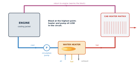
- Mount the heater and its pump low in the coolant circuit so they stay flooded; trapped air stops circulation and overheats the heat exchanger within seconds.
- Follow the maker's permitted mounting angles: the water outlet normally faces upward so air can escape.
- Plumb it in series with the cab heater matrix, using proper coolant hose and spring or constant-tension clips. Respect the flow direction arrow on the pump and on any non-return valve.
- Use antifreeze all year round at the engine maker's strength. Makers ask for at least 10% even in warm climates, as corrosion protection. Never run the heater with frozen coolant.
- Bleed the circuit thoroughly: cab heater control on full hot, bleed screws open, engine run until the thermostat opens, then top up. Poor bleeding is the commonest cause of faults after fitting.
- Exhaust, combustion air, fuel and electrical rules are the same as for air heaters. Most water heaters mount in the engine bay or under the floor, outside the cabin.
11.3 Faults specific to water heaters
| Symptom | Likely cause |
|---|---|
| Overheat shut-down within a minute of lighting | Air lock, low coolant, seized or disconnected circulation pump, closed heater valve |
| Runs but cab stays cold | Vehicle heater set to cold, matrix valve closed, coolant bypassing through the engine, vehicle fan not running |
| Short-cycles on and off | Circuit volume too small or flow restricted; the coolant near the heater reaches its limit at once |
| Fails to light, then locks out | As for air heaters: fuel, glow plug, carbon. Typically a fault shut-down follows if no flame appears within about 90 seconds |
| Coolant loss | Hose clips, pump seal, or (rarely) a perforated heat exchanger |
Burner servicing follows the same principles as an air heater, but these units are more compact and more model-specific. Get the workshop manual for the exact model before opening one, and fit new seals throughout.
12. Quick reference
12.1 Installation sign-off checklist
| Check | Done |
|---|---|
| Heater on steel plate with base gasket; no timber near the exhaust stub; plate sealed to floor | ☐ |
| Exhaust: short, falling, clamped, supported, drain hole at any low point, ends clear of body, no joints inside | ☐ |
| Combustion air: drawn from outside, end away from exhaust and spray | ☐ |
| Fuel: dedicated pickup, hard small-bore pipe, ends butted in joiners, clipped, clear of exhaust, pump outlet raised 15–35° | ☐ |
| Ducting: one outlet cannot be closed; return-air inlet unobstructed | ☐ |
| Electrical: fused at battery, adequate cable, crimped joints, no switch that can cut power when running | ☐ |
| EN 50291-2 CO alarm fitted and tested; extinguisher to hand | ☐ |
| Test run 20–30 minutes on high: no fuel weeps, no exhaust leaks, clean exhaust, normal shut-down | ☐ |
| Insurer informed | ☐ |
12.2 Tools for servicing
Multimeter; glow-plug box spanner; cross-head and hex bits that fit well; penetrating oil; small picks and a bent wire; wire brush and small drill bits (hand-held) for burner holes; plastic scraper; vacuum cleaner; blowlamp; sharp blade for fuel pipe; torch; gasket set.
12.3 Glossary
| Term | Meaning |
|---|---|
| ADR | The international rules for carrying dangerous goods by road, which restrict heater fitting and use. |
| CFPP | Cold filter plugging point: the temperature at which wax blocks a standard test filter. |
| Cloud point | The temperature at which wax crystals first appear in a fuel. |
| De-coke | Removing carbon deposits from the burner and heat exchanger. |
| Dosing (metering) pump | The solenoid pump that delivers a fixed shot of fuel per electrical pulse. |
| ECU / control box | The heater's control board. |
| FAME | Fatty acid methyl ester: conventional biodiesel. |
| Flame-out | The flame going out while the heater is running. |
| Gauze / atomiser screen | The mesh sleeve around the glow plug that wicks and vaporises fuel. |
| Hall sensor | A magnetic sensor used to measure fan speed. |
| HVO | Hydrotreated vegetable oil: a paraffinic renewable diesel to EN 15940. |
| Hz | Hertz: cycles per second. Here, pump ticks per second. |
| Lock-out | The heater refusing to start until stored faults are cleared. |
| NTC | A temperature sensor whose resistance falls as it warms. |
| Priming | Running the pump alone to fill the fuel line. |
| Standpipe | A dedicated fuel pickup tube fitted into a tank. |
12.4 Service log
Print this page or copy the table to keep a record of work done and settings used.
| Date | Running hours (if known) | Work done / parts fitted | Settings (min/max Hz, min/max rpm) | Fuel in use |
|---|---|---|---|---|
12.5 Sources and further reading
- Eberspächer, Airtronic / Airtronic M technical description, installation, operation and maintenance instructions (altitude limits, installation rules): manualmachine.com
- Heatso, Eberspächer air heater installation checklist (exhaust length and routing): heatso.com
- Webasto, Air Top 2000 STC specification sheet (approved fuels, voltage range): PDF
- Webasto, Air Top Evo user manual (heat exchanger ten-year replacement): manuals.online
- Mellor support note on HVO / EN 15940 paraffinic fuel in Webasto heaters: melloronline.freshdesk.com
- Eberspächer UK motorhome heating brochure (biodiesel compatibility by model): PDF
- OnTrack Outdoor, 5 kW diesel heater fault table (E-01 to E-10): manuals.online
- Vevor diesel heater manual, fault display table: manualslib.com
- YBW forum, 'Kerosene in a diesel heater?' (user experience and maker comment on additives): forums.ybw.com
- Heatso, fault codes for Espar / Eberspächer D2 and D4 heaters (code list and test values): heatso.com
- CamperKing, Webasto Air Top 2000 STC fault code finder: guides.camperking.co.uk
- Pango, bench diagnostic protocol for a 5 kW Chinese diesel heater (settings, pump delivery, sensor type): PDF
- YBW forum, 'Chinese heater output control' (how the min/max settings interact): forums.ybw.com
- Nationwide Fuels, HVO fuel EN 15940 specification: nationwidefuels.co.uk
- IEA-AMF, properties of paraffinic fuels: iea-amf.org
- Eberspächer Hydronic technical descriptions (coolant requirements, control behaviour, fault shut-down): slideshare.net and scribd.com
- IRS Publication 510, Excise Taxes (including fuel tax credits and refunds): irs.gov
- IRS, Instructions for Form 4136, Credit for Federal Tax Paid on Fuels: irs.gov
- Mississippi Department of Agriculture and Commerce, dyed fuel questions and answers: PDF
- CPA Practice Advisor, 'IRS Issues FAQs on Tax Relief for Dyed Diesel Fuel Highway Use', 29 October 2026: cpapracticeadvisor.com
- ATO, Excise duty rates for fuel and petroleum products: ato.gov.au (search the title)
- ATO, Fuel sold for domestic home heating; Fuel tax credits, non-business eligibility; Packaging or supplying fuel: ato.gov.au (fuel schemes pages)
- HMRC Excise Notice 75: Fuels for use in vehicles (search gov.uk for the current edition).
NOTE Diagrams in this guide are simplified schematic drawings made for explanation. They are not to scale and do not reproduce any one manufacturer's unit.
General guidance only. Your heater maker's own instructions always take priority.
New to some of the terms? See the glossary. Not sure where to start? Try start here.